The Non-Manifold Trap: Why Blender Hates Your CAD (And How to Bypass It)
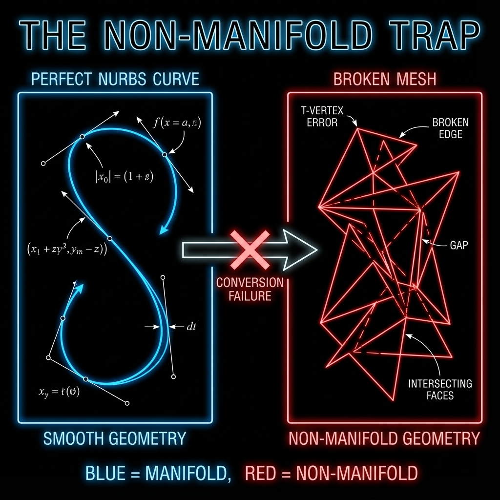
You export a turbine housing from SolidWorks, import the OBJ into Blender, and the mesh looks like it was hit by a grenade. Holes appear in solid surfaces. Faces flicker black. Parts that were perfectly aligned are now floating 0.001mm apart.
This isn't a bug in your CAD software. It's a fundamental mismatch between two mathematical worlds. Understanding why this happens is the first step to fixing it.
Part 1: The Mathematical Divide
How CAD Defines Geometry: NURBS
CAD software like SolidWorks, Fusion 360, CATIA, and Creo use NURBS (Non-Uniform Rational B-Splines) to define surfaces. A NURBS surface is a mathematical equation that describes a smooth, continuous surface with infinite precision.
For example, a simple cylinder in NURBS is stored as:
// Simplified NURBS representation of a cylinder
Surface Type: NURBS
Degree U: 2, Degree V: 1
Control Points: [
[(0, 0, 0), (r, 0, 0), (r, 0, h)],
[(0, r, 0), (r, r, 0), (r, r, h)],
...
]
Knot Vector U: [0, 0, 0, 1, 1, 1]
Knot Vector V: [0, 0, 1, 1]
The key property: there are no triangles. The surface is defined analytically. When you zoom in infinitely, you still see a perfect curve. This is why CAD can represent a 1-meter radius fillet with the same precision as a 1-micron chamfer.
How Mesh Software Defines Geometry: Polygons
Blender, Maya, Cinema4D, and game engines use polygonal meshes. A mesh is a collection of vertices (points), edges (lines connecting points), and faces (flat triangles or quads).
// A simple cube as a mesh
Vertices: 8 points at corners
Edges: 12 lines connecting vertices
Faces: 6 quads (or 12 triangles)
Every curved surface in a mesh is an approximation. A circle becomes a 32-sided polygon. A sphere becomes 512 triangles. The more triangles, the smoother it looks—but it's never mathematically perfect.
Part 2: What is Non-Manifold Geometry?
In topology, a manifold is a surface where every point has a neighborhood that looks like a flat plane. Think of it as asking: "If I were an ant standing on this surface, would I always feel like I'm on a normal 2D ground?"
Non-manifold geometry violates this rule. Here are the three most common violations that break CAD-to-mesh conversion:
| Defect | What It Looks Like | Why It Happens |
|---|---|---|
| T-Vertices | An edge ends in the middle of another face | Tessellator subdivides one face but not its neighbor |
| Bowtie Vertices | Two cones touching at a single point | Two separate bodies share one vertex |
| Interior Faces | A face inside the solid volume | Boolean operation leaves internal geometry |
| Zero-Area Faces | A triangle with 3 collinear points | Degenerate triangles from tangent surfaces |
| Flipped Normals | Black faces or inside-out surfaces | Face winding order inconsistent |
Error Messages You'll See in Blender
When you import a broken CAD mesh, Blender throws cryptic errors. Here's what they mean:
"Mesh has non-manifold edges"Edges shared by more than 2 faces, or boundary edges in what should be a closed solid.
"Cannot generate normals for mesh"Zero-area faces or degenerate triangles prevent normal calculation.
"Object has zero volume"Flipped normals or inside-out surfaces. Mesh doesn't form a valid closed solid.
Why This Keeps Happening: CAD → DCC Mismatch
The root cause is a fundamental workflow mismatch between CAD and mesh tools:
| CAD Tools | DCC Tools |
|---|---|
| Store as NURBS equations | Store as vertex/face lists |
| Designed for manufacturing | Designed for rendering |
| Tolerance: 0.001mm | Tolerance: "looks right" |
Part 3: The Export Settings That Matter
Most CAD-to-mesh problems can be mitigated with correct export settings. Here's a reference table for the major CAD packages:
| CAD Software | Best Export Format | Critical Settings |
|---|---|---|
| SolidWorks | STL (Binary) | Deviation: 0.01mm, Angle: 5° |
| Fusion 360 | OBJ or STEP | Refinement: High, Format: Binary |
| CATIA | STEP AP214 | Tessellation: 0.1mm sag |
| Creo/Pro-E | STEP AP242 | Chord Height: 0.005mm |
Pro Tip: Lower "deviation" / "chord height" values = more triangles = smoother curves. But also larger files and slower Blender performance. Start at 0.01mm for mechanical parts.
Part 4: Fixing Non-Manifold Geometry in Blender
If you're stuck with a broken mesh, here's how to diagnose and repair it manually:
Step 1: Select Non-Manifold Geometry
- Enter Edit Mode (
Tab) - Deselect all (
Alt + A) - Open Select menu → Select All by Trait → Non-Manifold
- Or use the shortcut:
Shift + Ctrl + Alt + M
Blender will highlight all problematic edges and vertices in orange.
Step 2: Common Repairs
Merge by Distance
M → By Distance — Welds vertices that are very close together (the "exploded view" fix). Set threshold to 0.0001m for precision parts.
Recalculate Normals
Shift + N — Fixes flipped normals by making all faces point outward consistently.
Fill Holes
F on selected edge loop — Creates a face to close gaps in the mesh.
3D Print Toolbox Add-on
Enable in Preferences → Add-ons. Provides automated "Make Manifold" repair that handles most CAD issues.
Step 3: Verify the Repair
After repairs, run Shift + Ctrl + Alt + M again. If nothing gets selected, your mesh is manifold-clean.
Part 5: When Manual Repair Isn't Worth It
For a single part, manual cleanup is tedious but doable. For a 500-part assembly, it's economically insane.
Consider the math:
- Average time to clean one part: 5–15 minutes
- 500 parts × 10 min = 83 hours of manual labor
- At $75/hr engineering rate = $6,225 in cleanup costs
This is where automated pipelines become essential. Tools that process native NURBS data—without intermediate mesh conversion—eliminate this category of problem entirely.
"The best way to fix non-manifold geometry is to never create it in the first place."
The Reific Approach
Reific was built specifically to avoid the mesh trap. We ingest native STEP and IGES files and process them using an industrial-grade NURBS kernel (the same technology used in CAM software for CNC machining).
Our rendering pipeline never asks you to triangulate your data. The tessellation happens server-side, with parameters optimized for visual fidelity—not for 3D printing or game engines.
The result: what you see in the viewport is mathematically identical to what you designed in CAD.
Key Takeaways
- ✓NURBS (infinite precision) vs meshes (discrete triangles) = fundamental mismatch
- ✓Non-manifold defects (T-vertices, bowties, flipped normals) break mesh tools
- ✓Export settings matter: use 0.01mm deviation for mechanical parts
- ✓Manual cleanup of 500-part assemblies costs ~$6,000 in engineering time
FAQ
What are manifold vertices in CAD?
in CAD and topology, a "manifold vertex" is one where the surrounding geometry forms a continuous surface without ambiguity. Specifically, if you zoom into a vertex, the surface around it should look like a disk (or a half-disk at a boundary). If a vertex connects two cones (like an hourglass shape) or has internal faces attached to it, it is non-manifold. CAD kernels strictly enforce manifold vertices; mesh modelers (like Blender) allow non-manifold ones, which causes export/import failures.
Why does Blender say "Cannot execute boolean operation"?
This error usually means your mesh has non-manifold geometry. Boolean operations (Union, Difference, Intersect) require water-tight, manifold meshes to calculate volume. If you have "non-manifold edges" or "flipped normals," the math fails. Fix it by running the "Select Non-Manifold" check and cleaning up the geometry first.
How do I fix "Blender cannot execute a non-manifold option"?
If you see an error related to non-manifold geometry preventing an operation: (1) Go to Edit Mode, (2) Select All, (3) Press Shift+N to Recalculate Normals, (4) Press M → "By Distance" to remove doubles. If that fails, use the 3D Print Toolbox's "Make Manifold" button. Just be aware that automated fixing might close holes you intended to keep open.
What is a non-manifold edge boundary in Blender 3D?
A non-manifold edge boundary is an edge that doesn't properly connect two faces in a way that forms a valid, "watertight" mesh. In Blender, this includes edges shared by more than two faces, edges belonging to only one face (open boundaries), or edges where face normals point in contradictory directions. These defects prevent operations like 3D printing, boolean modifiers, and proper rendering.
How do I find non-manifold geometry in Blender?
Enter Edit Mode (Tab), deselect all (Alt+A), then use Select → Select All by Trait → Non-Manifold. The keyboard shortcut is Shift+Ctrl+Alt+M. Blender will highlight all non-manifold edges and vertices in orange. You can also enable the 3D Print Toolbox add-on for additional diagnostics.
How do I fix non-manifold edges in Blender?
The most common fixes are: (1) Merge by Distance (M → By Distance) to weld vertices that are very close together—use 0.0001m for precision parts; (2) Recalculate Normals (Shift+N) to fix flipped faces; (3) Fill holes manually by selecting edge loops and pressing F; (4) Use the 3D Print Toolbox add-on's "Make Manifold" button for automated repair.
My CAD import shows "92 non-manifold edges" — how do I fix this?
Large numbers of non-manifold edges typically come from tessellation errors during export. First, try re-exporting from your CAD software with tighter tolerance settings (0.01mm deviation). If that doesn't help, use Blender's Merge by Distance with a small threshold, then run Select Non-Manifold again. For persistent issues, the 3D Print Toolbox's automated repair handles most cases.
What causes a non-manifold defect in CAD exports?
Non-manifold defects arise from the NURBS-to-mesh conversion process. CAD surfaces are mathematically perfect, but mesh tessellation creates discrete triangles that may not align perfectly at boundaries. Common causes include: different tessellation settings on adjacent faces, boolean operations leaving internal geometry, tangent surfaces creating degenerate triangles, and tolerance mismatches between CAD and mesh formats.
Can I procedurally repair non-manifold geometry in Blender?
Yes. The 3D Print Toolbox add-on (Preferences → Add-ons → search "3D Print") provides one-click "Make Manifold" repair. For scripted workflows, you can use Blender's Python API with bpy.ops.mesh.fill_holes(), bpy.ops.mesh.remove_doubles(), and bpy.ops.mesh.normals_make_consistent() in sequence. However, automated repair may not preserve all geometric intent.
Why doesn't Blender support STEP natively?
Blender is a mesh-based tool designed for animation and VFX. NURBS support would require a completely different geometry kernel—which is technically complex and outside Blender's core use case.
Is OBJ or FBX better for CAD export?
OBJ is simpler and more widely compatible. FBX carries more metadata but can introduce scale/axis issues. For textureless mechanical parts, OBJ is usually safer.
Can I use Blender add-ons to import STEP directly?
CAD Sketcher and BlenderBIM offer basic STEP import, but they still convert to mesh internally. The non-manifold issues remain.
Does STEP export support non-manifold geometry?
STEP files store NURBS geometry, which is inherently manifold. However, when a mesh tool imports STEP, it must tessellate (convert to triangles), and this conversion process can introduce non-manifold artifacts. The original STEP geometry is valid—the problem arises during mesh conversion.
Skip the cleanup. Upload the STEP.
Reific skips the CAD→mesh cleanup: upload STEP/IGES and render without wrestling with non-manifold geometry.
Try Reific Free